of an Atomic Force Microscope
 |
| Before
constructing our smaller
AFM model to be used in class labs, we began
by making a much larger model used to demonstrate the principles of
atomic force microscopy. While this first model was much simpler in
design, it was still a fully functioning model and data could be
collected either from direct measurement of the laser difflection (as
was done in labs) or through
an oscilloscope. |
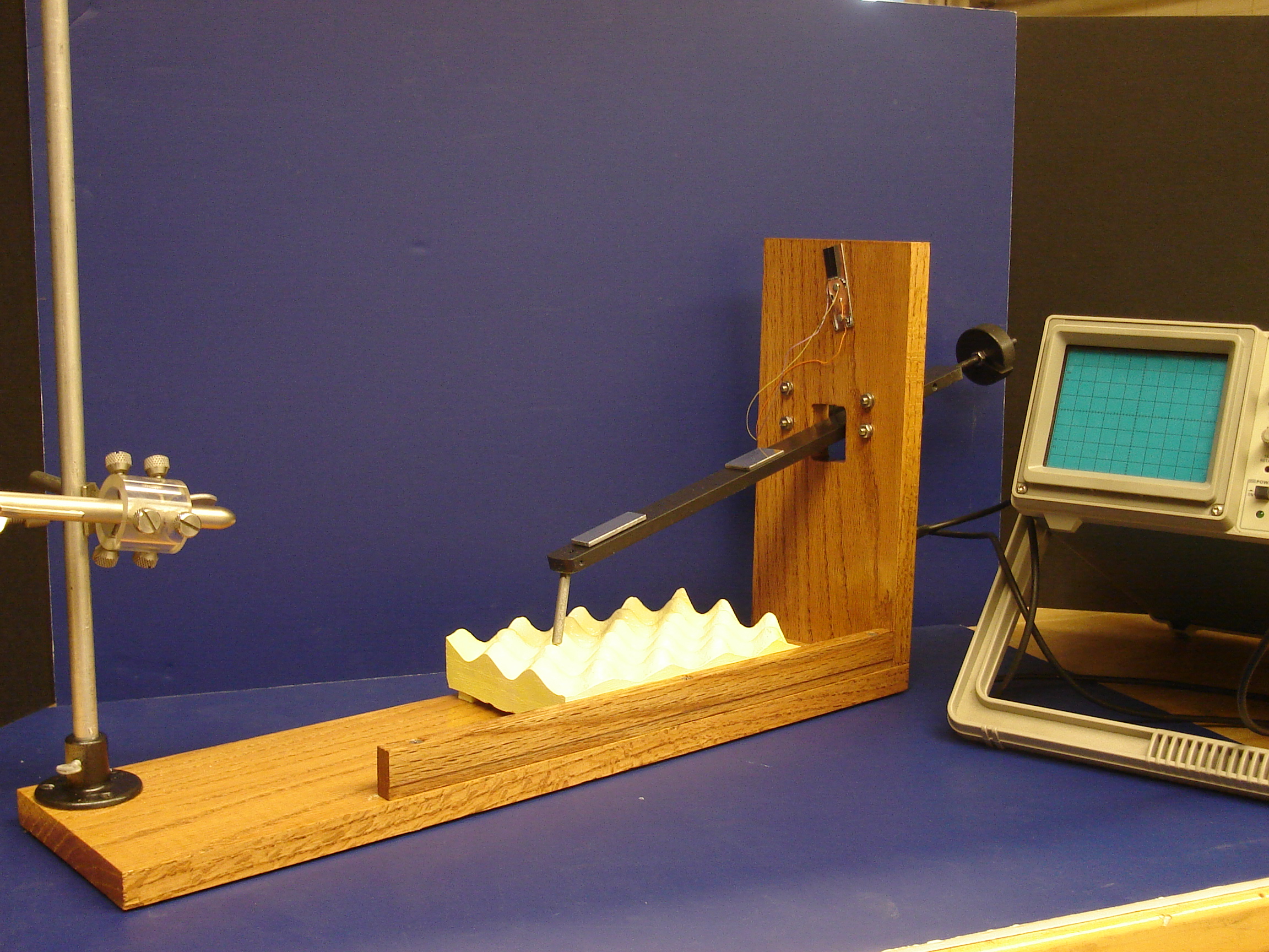
| To make this
larger model, we used a wooden frame to hold a 40 cm aluminum arm. The
tip was formed by rounding the end of a plexiglass rod and two
mirrors were used to reflect the laser beam onto a photocell attached
at the top of the wooden from above the cantilever. The 'sample' was
made by taking a plaster of paris mold of a piece of foam. Two strips
of tefflon were glued to the bottom of the sample
so that it could glide smoothly when measurements were taken. In
addition, a small weight was attached to the back end of the arm to
ensure the lightest possible contact between the tip and the sample. |
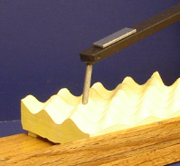
| Photocell |
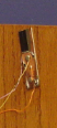
Demo
Tip and Sample |
Counterbalance |
 |
 |
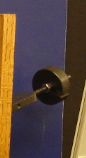 |
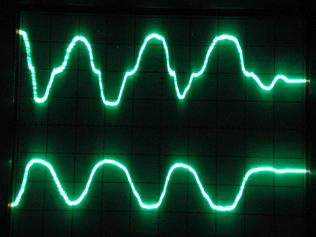
| You may have
noticed that the aluminum arm has two mirrors. We decided that, since
this model was going to be used in classroom demonstrations, we would
have it perform as many functions as possible. The first mirror,
closest to the tip of the cantilever, was used to reflect the oncoming
laser beam to the photocell, thereby allowing for an oscilloscope
reading of the laser difflection (see picture below). The second mirror
was used to reflect the laser beam over the wooden frame an onto a
screen. By having the beam projected several feet away onto a large
screen, students could see the amplified movement of the beam and could
better understand the principles behind AFM measurements. |
| Oscilloscope Reading from
Demo AFM |
 |
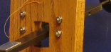
| In addition to
having two
mirrors, the model's arm itself could be adjusted to provide a longer
or shorter cantilever. The arm was allowed to pivot using two pointed
screws which rested in small divots drilled into the aluminum arm. We
made three pairs of such divots, each 5.5 cm apart down the length of
the
arm providing cantilever lengths of 26.75 cm, 31.75 cm, and 36.75 cm.
In general, we found
that the 31.75 cm length arm worked the best in general, but each was
used to
demonstrate
how cantilever lengths affected the deflection of the laser beam and
the sensitivity of the AFM. |
| Cantilever Length Can Be
Adjusted Using Small Divots Drilled in Arm |
 |