Working
AFM Model
Construction
D) Sample(s)
AutoCAD Drawings
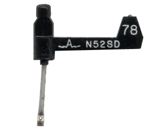
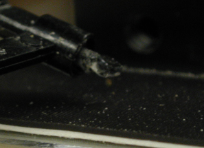
| Our tip is a
shortened phonograph stylus, specifically an Astatic N52 stylus. We had
previously tried bent sheet metal, a thumb tack, and victrola stylus
with little luck. Although the small cantilever of the phonograph
stylus was rather short to begin with, we found that nearly the entire
length of the arm needed to be cut off in order for the tip to be
suitably sensitive. |
| Phonograph
Stylus Before Modification |
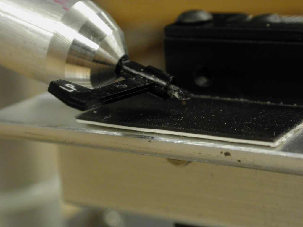
Final
Phonograph Stylus |
 |
 |
(Back
to
Top) (Back
to
Main Page)
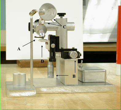
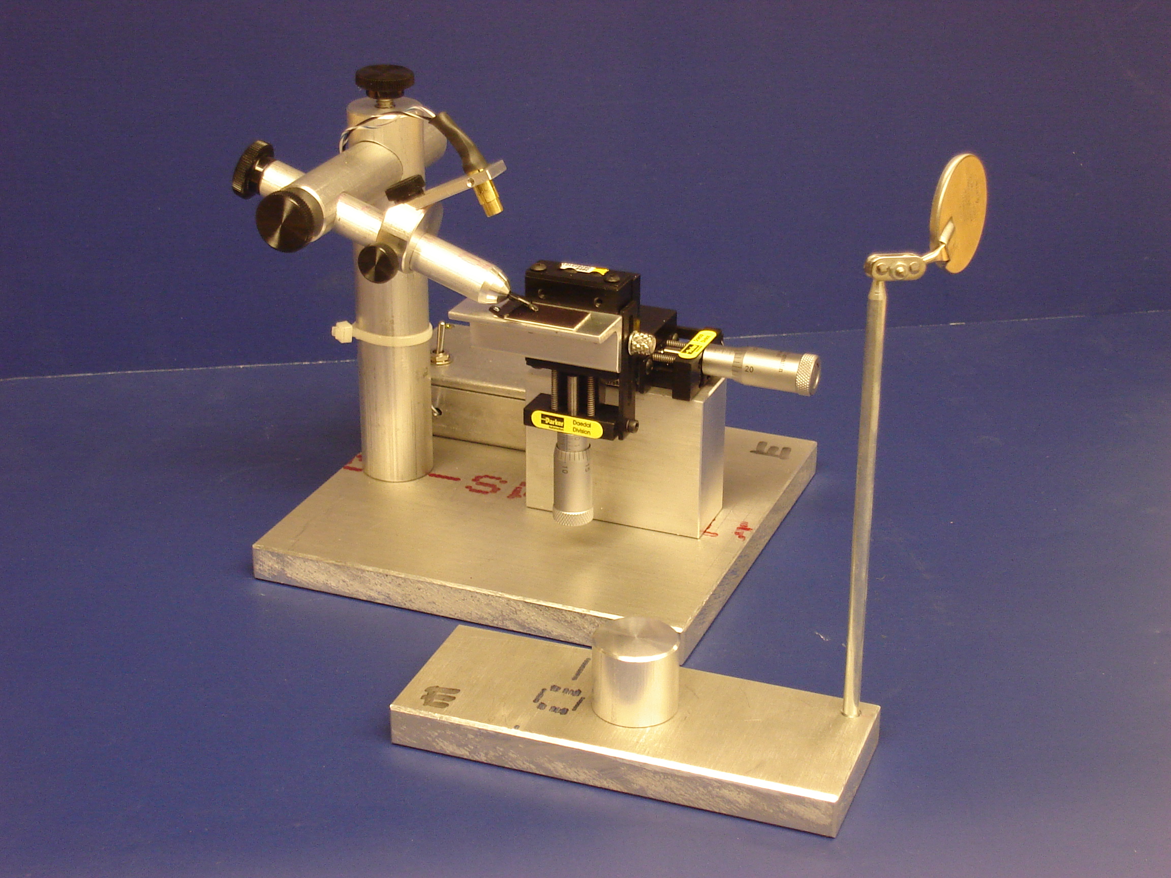
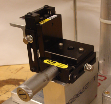
| The frame was
manufactured by the UVM Physics Dept. Machine Shop using conventional
methods and was fabricated almost entirely from 6061 Aluminum stock.
The housing for the laser and lense was made from brass telescoping
tubing. The manual positioners were specifically two 3900 Series (1.25 inches wide) miniature stages from Edmund Optics. A z-axis adapter was also necessary in order to have the x/z axis adjustment we needed rather than the usual x/y. We accidentally ended up with the English version rather than metric, but it turned out to be a lucky mistake simply because the wider spaced lines were easier to read in dim light. |
 |
 |
(Back to Top) (Back to Main Page)
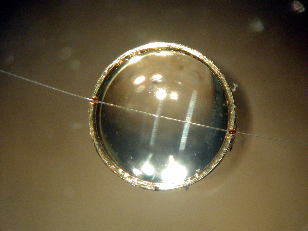
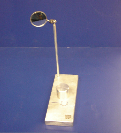
| Our laser
source was a 10 mW laser diode assembled with a small lens. The lens
also had a quartz fiber cross-hair attached which made
measurements considerably easier. The small mirror on the tip of the
AFM phonograph stylus was made from small chips of polished silicon
wafer. Our final mirror was simply an adapted round dental mirror. |
| Laser
Lens with Quartz Fiber Cross-Hair |
Large
Mirror |
Small
Silicon Mirror |
 |
 |
 |
(Back
to
Top) (Back
to
Main Page)
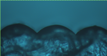
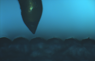
| Initially, we
tried Ronchi gratings and experimented with sandpaper. The 400 grit
sandpaper seemed to work best and several graphs
were made from the data collected during test runs. However, the
irregular sandpaper surface was not ideal for our introductory lab -
where we wanted to be able to predict the size and shape of the grooves
before scanning - and so we continued to experiment with different
materials. By
chance, we discovered a holographic post-card whose surface was made of
a regularly grooved plastic. The pieces of postcard proved to be the
best samples we had tried thus far and so they remained as our primary
samples used in classroom labs. |
| 10x
Image of Plastic Sample |
Sample
and Tip |
 |
 |
<>
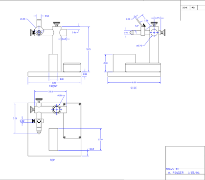 |
AutoCAD Drawings |
| (Click Here)
|