Riparian Land Use and Land Cover Mapping
Standard Operating Procedures (SOP)

Version 2.4
Jarlath O'Neil-Dunne
Keith Pelletier
802.656.3324
Last updated: August 12, 2005
This paper outlines the standard operating procedures (SOP) for 1:5000-scale riparian land-use/land-cover (LULC) mapping in Vermont. This document is required reading for all analysts assigned to the project.
I. Training
A. Prerequisites recommend for analysts working on the project:
1. Introductory GIS course
2. Familiarity with the Vermont landscape and the major LULC classes in Vermont
B. Supplementary Training
1. Analysts should complete the following ESRI Virtual Campus courses.
a. Creating and Editing Geodatabase Features with ArcGIS 9
b. Creating and Editing Geodatabase Topology with ArcGIS 9
2. ESRI Global Login accounts are necessary for enrollment in all Virtual Campus courses. This account is free of charge and can be created at http://campus.esri.com/. To obtain course codes contact Steve Cavrak and provide him with the course names. He will then issue access codes.
C. Project familiarity
1. Prior to beginning work analysts should familiarize themselves with the project by examining existing riparian LULC layers that have been subjected to QA/QC.
2. Prior to beginning work on the project analysts should digitize LULC for a test area and have it examined by a reviewer.
II. Storage & Database
A. Storage
1. Drive mapping.
a. All project-specific data and documents are stored on the SAL Server in the riparian folder. To access this folder map a drive letter R to \\SAL\riparian.
b. All general data and documents are stored on the SAL Server in the riparian folder. To access this folder map a drive letter X to \\SAL\data.
c. In ArcCatalog, direct connections should be made to R: and X:\vt.
2. Structure. The riparian folder is organized into five subfolders:
a. Data – Ancillary data layers (those that compliment imagery in the image interpretation process), layer files with symbology, separate geodatabases for each riparian mapping zone, the geodatabase schema, and the project metadata template.
b. Docs - Documentation related to the project, including the SOP, project proposal, Quality Assurance Project Plan, VCGI LULC codes, Anderson Classification paper, and others.
c. Maps – The ArcMap template, along with all maps.
d. Temp – Storage of temporary or intermediate data.
e. Tools – A single ArcToolbox containing models or scripts in supports of tasks commonly carried out in the project.
B. Geodatabase
1. A separate personal geodatabase should be created for each riparian LULC mapping zone. The geodatabase should be named after the buffered stream’s main channel.
2. The process of setting up the geodatabase, including creating the appropriate feature datasets, feature classes, topology, and metadata is facilitated by importing the project geodatabase XML schema, Riparian_LULC_Schema, located in the project’s Data folder. Please refer to Appendix A, Importing the Geodatabase Schema, for complete instructions.
3. After the XML Schema has been imported several updates must be made:
a. Features must be added to the Buffer feature class (Section III-B)
b. Metadata elements must be updated (Section IV).
III. Image interpretation
A. ArcMap Setup
1. An ArcMap template, LULC_template.mxt, is stored in the Maps subfolder. This template contains symbology for the Buffer and LULC layers along with all of the ancillary layers necessary for interpretation. What is not contained in the map template is the uncompressed imagery. The imagery, both VMP orthos and NAIP orthos, present in the template are compressed and should be used for orientation only, NOT for LULC mapping.
2. Opening the template.
a. In ArcCatalog double-click on LULC_template.mxt. This generates a new, untitled ArcMap document.
b. Save the ArcMap document as the name of the stream that is being mapped (i.e. Winooski.mxd) in the Maps subfolder.
3. The data source for several layers in the new ArcMap document must be updated. To update the source for a layer, right-click on the layer, click on the Source tab, click on the Set Data Source button. The layers listed below should be updated as follows:
a. Buffer – The Buffer feature class in the geodatabase for the current stream mapping zone.
b. LULC– The LULC_Riparian feature class in the geodatabase for the current stream mapping zone.
c. VHD (line) – The Water_VHD########_route_rch line feature class from the Vermont Hydrography Dataset (VHD) where ######## is the 8–digit HUC. The appropriate VHD features class can be determined by referring to the 8-digit hydrologic unit code (HUC) in the Watersheds layer. VHD data is stored in one of the VCGI databases under //sal/data/.
d. VHD (poly) – The Water_VHD########__region_wb polygon feature class from the Vermont Hydrography Dataset (VHD) where ######## is the 8–digit HUC. The appropriate VHD features class can be determined by referring to the 8-digit HUC in the Watersheds layer. VHD data is stored in one of the VCGI databases under //sal/data/.
4. The uncompressed VMP and NAIP orthos must be added to the ArcMap document for use in image interpretation.
a. The model, Orthophoto Tile Selection, located in the Riparian_LULC Toolbox, automates the process of identifying VMP and NAIP tiles. The only input required is the Buffer layer. The output consists of two tables, one for VMP, one for NAIP, that list the relevant tiles.
i. Uncompressed VMP orthos are on CDs in the SAL’s data cabinet.
ii. Uncompressed NAIP orthos are on the external Maxtor hard drive labeled Data under NAIP/Full/.
b. NAIP orthophotos must be reprojected to the VT StatePlane NAD83 coordinate system. This can be accomplished in batch mode using ERDAS IMAGINE. Refer to the following ERDAS Technical Support article.
5. Editing Settings
a. Selectable Layers
i.
The Selection tab below the ArcMap table of contents can be
used to set the layers that are selectable via the Edit Tool  or Select Features Tool
 .
.
ii. The selectable layers should be set to the layer to be edited to ensure that incorrect layers are not selected and to improve the usability of the polygon edit tools. Features should be cleared (unselected) when editing of that feature is complete. A Clear Selected Features button can be added to the Editor toolbar by clicking on Selection in the Customize option under Tools and dragging the button to the main toolbar.
b. Sticky move tolerance
i. The sticky move tolerance should be set prior to editing. It can be settings can be accessed from the Editor toolbar, Editor > Options. In the Editing Options window click on the General tab.
ii. The sticky move tolerance should be set to 50,000 pixels. This high tolerance will prevent the inadvertent movement of selected polygons which can produce several topological errors.
c. Snapping
i. The Snapping Environment is accessed via the Editor Toolbar Editor > Snapping. The Snapping Environment should be checked prior to beginning each editing session.
ii. The snapping settings for the template are to snap to vertices for the LULC layer, and no snapping settings for all other layers.
iii. The snapping environment will need to be adjusted when creating polygons that are completely enclosed within another polygon using the Cut Polygon task. In this case the snapping environment should be set to sketch vertices under the edit sketch option. The sketch must snap to the polygon end point for the Cut Polygon task to succeed.
B. 800 Meter Buffer
1. All LULC mapping will occur within an 800m buffer on either side of the stream(s) selected for mapping.
2. The 800m buffer should be created from the Vermont Hydrography Dataset (VHD). For wider streams where VHD polygons are present the buffer should be delineated from the edges of the polygons. Narrower streams whose banks cannot be determined from imagery and thus do not have polygons representing their banks should be buffered based on the stream center line.
3. The following layers should be used in the buffering process:
a. For stream polygons the layer VHD (poly), which corresponds to the VCGI polygon features class Water_VHD########_region_wb.
b. For stream centerlines the layer VHD (line), which corresponds to the VCGI the line feature class Water_VHD########_route_rch.
4. The buffer should be created by selecting the appropriate polygons and lines and then buffering them using the Buffer tool that is accessed via the Editor toolbar. Refer to Appendix B.
C. Image interpretation
1. Methodology
2. Standards and Methodology
a. Class assignment will be primarily made on analyst recognition using the photointerpretation keys as a reference. Ancillary layers will be consulted to aid in the identification of certain classes (see Section III-C-3 below). The Image Interpretation Matrix (Appendix D) serves as a quick reference for image interpretation.
b. LULC class assignment is based on the Anderson Level 1 classification scheme, (Anderson et al, 1976); with selected classes further refined to Levels 2 and 3, resulting in 14 classes. Refer to Appendix C for a complete description of the classes.
c. All image interpretation will be done in ArcMap using a map derived from the ArcMap template, LULC_template.
d. The primary base layer for digitizing is the uncompressed Vermont Mapping Program’s (VMP) 1:5000-scale digital orthophotography quadrangles (DOQs). The National Agricultural Imagery Program (NAIP) orthophotographs will supplement the DOQs for proper identification of LULC features. All features digitized from the VMP orthos should be cross reference with the NAIP orthos due to the fact that the NAIP orthos are more current that the VMP orthos. Features should be digitized from the NAIP orthos if they differ from the VMP orthos and if this difference can be attributed to temporal change. For example, if what appears to be an agricultural field in the VMP orthos shows up as a residential urban area in the NAIP it should be assigned to the Urban-General (10) class.
e. All features will be digitized at a scale no coarser than 1:5000.
f. The minimum mapping unit (MMU) for the LULC mapping project is 0.1 hectares (~ ¼ acre). Features that are smaller than the MMU should be grouped with surrounding features.
i. The MMU can be created from the Draw toolbar with the New Rectangle tool and will be 0.1 hectares when the width and height properties of the graphic are set to 31.63 meters.
ii. This graphic is useful when overlain on an area to ensure that the feature meets the MMU.
g. Editing
i. The primary editing task in the Editor toolbar for digitizing the LULC features is Auto-Complete Polygon. In general, the use of the Create New Feature task when digitizing adjacent features should be avoided as it likely to create topological errors due to overlapping polygon boundaries.
ii. Features should be digitized so that they extend just beyond the Buffer layer. The LULC layer will be clipped to the Buffer layer once mapping is complete.
iii. When new polygons are created the LULC field should have the proper class assigned from the LULC_Code domain. If there is any uncertainty with regards to class assignment the second most likely class should be entered in the LULC_Alt field. Comments can be entered in the Notes field.
h. Image enhancement can improve the interpretability of an image. Some enhancements, while degrading the overall appearance of an image, can substantially improve the interpretability of a single class or set of features.
i. Adjusting the brightness and contrast can be accomplished using the Effects toolbar. Bright features such as urban areas are generally more interpretable when the contrast and brightness values are set low. Vegetation is generally more interpretable when the contrast is increased. Dark features such as water, wetland, and shadows are typically easier to discern when the brightness is increased and contrast decreased. These are only general guidelines and the image interpreter should experiment with settings.
ii. In addition to the Effects toolbar the histogram settings can be adjusted by accessing a layer’s Symbology properties. A Stretch Type of None typically provides the most realistic view when looking at orthophotos, but a Standard Deviation stretch provides the most flexibility when used in conjunction with the Effects toolbar. Generally urban and barren features are best interpreted using a Stretch Type of None, while vegetation is best interpreted using Stretch Type of Standard Deviation.
3. Ancillary data. In many cases ancillary layers can prove extremely All layer names in italics refer to layers in the ArcMap template. This information is presented in a condensed form in Appendix D.
a. Urban-General (10): The E911 Sites can be used to identify urban structures. Driveways can be used to identify driveways and provide an indication of urban features.
b. Urban-Transportation (14): The best layer for identification of transportation features is Roads. This layer represents the road centerlines based on E911 data. It is imperative that analysts perform a careful visual inspection of the centerline to ensure that it follows the center of the roadway. Most road classes should be digitized; however some classes may require careful inspection, such as 99 (unknown). Private roads (code 9) are included in this layer, unlike other transportation layers. It might also be useful to buffer a road’s centerline based on width measurements along the roadway. The road buffer can be created by selection of the road segment and the use of the Buffer tool in the Editor Toolbar. This buffer may be useful in delineating transportation features when the road is obscured by tree canopy.
c. Agriculture (2, 21, & 22): USDA Common Land Unit (CLU) polygons indicate land owned by farmers who participate in NRCS and FSA programs; however, not all polygons in the CLU layer are agricultural land. Forest, brush, structures and other features are often included in the CLU layer. Fields that are actively managed for crop production, to include hay, traditional crops, orchards, berry farms, and tree farms, have a CLUSCD value of ‘2’. While the CLUSCD codes are supposed to adhere to the Anderson classification system a complete review of the CLU data in Vermont indicates that values aside from ‘2’ do not accurately reflect LULC. Despite this limitation the CLU layer can be extremely valuable when used in conjunction with imagery to identify LULC. CLU polygons with a CLUSCD code of ‘2’ should be used to identify features classified as Agriculture-Hay/Crop (21) or Agriculture-Orchards (22), which for the purposes of this project only includes managed hay and crop fields. Because the CLU polygons were created from dated imagery the 2003 NAIP should be used to confirm that the field has not been converted to Urban-General (10) or left idle long enough to justify classifying it as Brush (3). Features that fall within CLU polygons whose CLUSCD value is not ‘2’ and appear “field-like” or grassy are likely pasture or other agricultural land and should be assigned to the Agriculture-General class (20). Other features that fall within the CLU polygons, but do not appear to be agricultural fields should be assigned to the appropriate LULC class; this includes assigning structures to the Urban-General class (10) and permanent roads to the Urban-Transportation class (14). The Roads layer and comparisons between VMP orthophotos and the NAIP imagery should give an indication if a road through or between agricultural fields is a permanent feature.
d. Forests (4): Wetlands and Hydric Soils layers should be consulted to assess if the forested area is a wetland. Be advised that neither of these layers definitively indicates the presence of a wetland.
e. Water (5): Surface waters can be easily identified with the assistance of the VHD layers, which represent the most current surface water data for the state. In many cases water features can be copied from the VHD (poly) layer and pasted into the LULC layer.
f. Wetlands (6): Both the Wetlands layer (based on the Vermont Significant Wetlands Inventory) and the Hydric Soils layer provide and indication that wetlands may exist. However, neither of these layers is deemed accurate enough for determining the precise boundary of a wetland feature.
g. Barren (7): The Mineral Sites layer can be used to identify mineral extraction activities. However, some of the points are outdated or geographically inaccurate, so caution should be applied when using this layer.
IV. Metadata
A. Identification > General > Abstract:
1. The [STREAM NAME] should be changed to the name of the stream.
2. There are two versions of the second paragraph in []. Choose the first one if the layer is pre-release, the second one if final release. For final release indicate the overall accuracy of the dataset.
B. Identification > Citation > Citation Title:
1. The [STREAM NAME] should be changed to the name of the stream.
2. In ( ) following the stream name, enter Pre-Release if the version is a preliminary release of the layer.
C. Identification > Status: Update the Progress field to reflect the status of the layer.
D. Identification > Keywords > Theme: Add the stream name to the Place.
E. Data Quality > General > Logical Consistency Report: The reviewer should indicate the number of topology errors and sliver polygons.
F. Data Quality > Attribute Accuracy > Accuracy Report:
1. Indicate the number of mislabeled polygons
2. Provide the complete error matrix and accuracy assessment statistics.
G. Data Quality > Process Step:
1. The Process Contact should be updated for each process step. Only the person’s name is needed.
2. The Process Date should be updated to indicate the date the process was completed with the YYYYMMDD date format.
H. Entity Attribute > Detailed Description > Attribute:
1. Confirm that both the LULC_Alt and the Notes fields have been deleted.
2. Check for and delete duplicate fields.
3. After conversion to Shapefile confirm that the Shape_Length field has been converted to Perimeter and the Shape_Area field to Area.
I. Metadata Reference > General > Metadata Review Date: Enter the date the metadata was reviewed.
J. Metadata Reference > Extensions: A second extension could be created when importing the template; delete metadata extension 2 of 2.
V. Quality Assurance and Quality Control (QA/QC)
A. Analyst
1. Make a backup copy of the entire geodatabse layer.
2. In editing mode convert multipart features to singlepart.
a. Select all LULC features
b. Click on the Explode tool located on the Advanced toolbar.
3. Run the QA/QC tool to:
a. Repair geometery.
b. Check for the presence of sliver polygons. Sliver polygons will typically have an area less than the MMU.
c. Validate topology
4. Fix errors
a. Merge sliver polygons.
b. Fix topology errors.
5. Review each polygon that was assigned an alternate LULC class. If a final determination can be made delete the alternate LULC class code. If not, leave the alternate LULC class code.
6. Conduct a cursory review of the entire LULC layer at a scale of 1:5000. Check for:
a. LULC class assignment.
b. LULC class boundaries.
7. Clip the LULC layer to the Buffer layer.
8. Dissolve the LULC layer by LULC class.
B. Reviewer
1. All QA/QC should be done by a representative other than the original analyst responsible for digitizing the LULC.
2. A 500m x 500m polygon grid will overlay the LULC layer and each grid cell will be reviewed at a scale of 1:5000. When the entire cell has been reviewed, it will be labeled complete by the reviewer.
3. The reviewer will make the final decision on any disputed LULC assignments.
4. A thorough review of the metadata will be conducted as part of the QA/QC and any errors or corrections will be the responsibility of the photointerpreter.
References
· Proposal
· Anderson LULC classification
Appendix A: Importing the Geodatabase Schema
1) Create a new personal geodatabase
a) In ArcCatalog from the File menu click New > Personal Geodatabase
b) Right-click on the geodatabase and select Rename. Rename the geodatabase to reflect to the name of the stream that you are mapping (i.e. Winooski).
2) Importing the XML schema
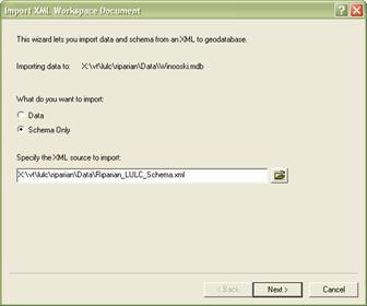
a) Right-click on the geodatabase and choose Import > XML Workspace Document
b) In the Import XML Workspace Document window under What do you want to import select Schema Only. For Specify the XML source to import navigate to X:\vt\lulc\riparian\Data\Riparian_LULC_Schema.xml. Click Next then Finish.
3) In the ArcCatalog Contents view of the new geodatabase, right-click > Refresh. The geodatabase now contains the following:
a) LULC_Domain (table) – the LULC classes used in the project.
b) LULC (feature dataset) – container for the feature classes and topology.
c) Buffer (feature class) – shell for the 800m buffer.
d) LULC_Riparian (feature class) – shell for the LULC mapping.
e) LULC_Topology (topology) – topology rules:
i) LULC_Riparian must not have gaps.
ii) LULC_Riparian must not overlap.
iii) LULC Riparian and Buffer must cover each other.
Appendix B: Creating the 800 Meter Buffer
1) Setup
a) Start Editing in ArcMap and insure that you have selected the path to the appropriate geodatabase in the Start Editing window.
b) Set the Target in the Editor toolbar to the Buffer feature class.
c) Both the VHD (line) and VHD (poly) layers in template should be set to the appropriate source layers. Refer to Section III-A-3 for instructions on this.
2) Selecting streams
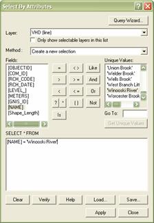
a) Under Selection > Select by Attributes create a query based on the VHD (line) line layer to select the appropriate stream centerlines. For example:
b) Under Selection > Select by Location create a query that selects all of the features from the VHD (poly) layer that intersect the selected features from the VHD (line) layer.
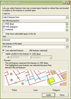
c) The appropriate stream centerlines and corresponding polygons should now be selected.
3) Buffering
a) Confirm that the Target layer in the Editor toolbar is set to the Buffer layer.
b) On the Editor toolbar select Editor > Buffer.
c) In the Buffer window enter 800 as the distance.
d) This will typically create multiple overlapping buffers, which are all selected. To merge these multiple buffers make sure they are still selected then from the Editor toolbar select Editor > Merge
4) Save your edits.