Types of Environmental Simulation Models
Simulation models are frequently produced for either direct viewing or photographic images. Direct viewing models hold a high potential for preservation planning and public involvement. Many city planners use such models to evaluate the impact which proposed buildings may have on views of the skyline or within the city and to test how setbacks will affect the amount of sunlight on streets and in parks and to predict wind conditions. Environmental simulation models may also be used by planners and review boards to test conformance with existing zoning and historic district ordinances, as well as to help develop or refine such ordinances. To insure fairness, such models should be accurate and objective with specified tolerances and conventions.
As an educational tool, models can offer insights into basic planning concepts. For example, densities, lot-coverage ratios, set-backs, types of use and massing may be illustrated within identifiable settings and the effects of altering these legal parameters may be perceived from a pedestrians viewpoint. Modeled areas may also be used as analogs to illustrate the types of change that may occur in other areas as well.
Images produced from studio models of landscapes may offer powerful, publishable means of previewing options for the future. While the Berkeley Environmental Simulation Laboratory and others have produced impressive results on film and video using sophisticated optical equipment and "special effects" filming techniques, the work at the University of Vermont has explored methods to produce effective print and slide images with basic 35mm camera equipment. These techniques are discussed later. Many creative shortcuts and effects may be utilized to produce images in a studio that could not be used for models which would be viewed directly. The highly detailed studio models are however, inevitably fragile and vulnerable.
Key Sites and Impacts
When planning a project and evaluating a potential site to model, several questions should be asked. Where is change likely to occur? A specific project might be planned for a specific site, but what will be its impact on the surrounding area? What about indirect impacts? How can these impacts be shown?
History
When the objective is to plan and review proposed changes to an existing landscape, a thorough understanding should be gained of the history and evolution of the site. Historical research, especially based on pictorial evidence and old maps, is a critical component of all landscape preservation projects. When one walks a site with an awareness of its changes and evolution, the visual clues that create a sense of place and tell of its history may be more apparent. These visual clues should be noted and photographed for future reference.
Viewpoints
When visiting a prospective site it is important to analyze how the landscape is actually perceived. Draw a sketch map of the site and walk (or drive) along the frequently traveled routes to all important destinations. Make note of the locations where vistas unfold. What is the background view? Record each of these vistas from a typical viewer's perspective with a panoramic series of photographs. Record the sequences of views one experiences when moving through the site. By analyzing these views, it may become apparent that some viewpoints are especially memorable and are most identifiable by the public. (Watch how people view the site. Exactly where and at what do they frequently look?) Note the locations of these popular viewpoints. The site may also have important vantage points which may not be accessible or are infrequently visited. These should also be recorded with panoramas. Are changes planned which may create new popular viewpoints? How does one's perception of the site change by time of day? day of week? season? type of weather?
Area to be Modeled
What are the issues to be addressed by the simulation project. Which specific sites are under review or analysis? What are the changes or threats? How will these be physically manifested? From which popular viewpoints will these issues be reflected? How will they be depicted in the model? What model views will illustrate the issue? Is the model to be used strictly to produce simulated images or will it be used for direct viewing? Does the site have a natural concavity or structures which could define the model's bounds? (Most sites will require separate backdrops extending to the horizon for each model view.) How many (or few) viewpoints (and backdrops) are necessary? How much detail should be depicted in the backdrops?
Scale
The following factors may influence the choice of the scale of model:
Large scales offer the potential for more realism of details, while smaller scales allow broader spaces to be modeled. Modeling supplies are available in architectural scales (from 1/2 to 1/32 inch to the foot), engineering scales (1/20 to 1/100 inch to the foot ), and in model railroad scales (HO is 1:87, N is 1:160, and Z is 1:240.) If a simulation is to address such issues as alterations to building facades and streetscape changes, a scale of 1/16 inch to the foot (1:196) offers sufficient detail, while allowing a room-sized model (six by nine feet) to represent slightly less than 50 acres. For modeling larger landscapes, a scale on the order of 1/50" to the foot would be necessary, however the amount of detail and realism from a simulated pedestrian's viewpoint would be limited. Indeed many people viewing 1/50 scale models feel as though they are viewing the site from an airplane, while at 1/16 scale, the pedestrian viewpoint is readily imaginable. Models built in scales smaller than 1/16" are also more difficult to photograph with 35mm cameras and standard macro lenses.
Comparison of Model Scales
| scale | scale ratio | model area per square acre | model building height per 10 foot story |
| 1" equals 16' | 1:192 | 13" X 13" | 0.625" |
| 1" equals 32' | 1:384 | 6.5" X 6.5" | 0.313" |
| 1" equals 50' | 1:600 | 4.2" X 4.2" | 0.20" |
Site Documentation and Mapping
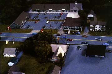
The accuracy and potential for realism in a model depends on the accuracy, quality, and quantity of information available about a site. Sources of geographic information for urban areas include municipal tax maps, aerial photos, and land surveys. In rural areas, U. S. G. S. quadrangle maps may be the only information available. While quadrangle maps can used to develop a base map, the margin of error in elevations will be dictated by the 20-foot contour interval information. Hopefully computer-based geographic information services (GIS) information could contribute as well.
While the general shape of the land may be modeled, additional information must be obtained to depict such features as roads and ditches. Ideally the entire site would be surveyed by tape and transit to gather information on elevations, locations of streets, buildings, trees, signs, utility poles, types of ground cover, et cetera, but for most projects, the cost of such a survey would be prohibitively expensive. An alternative is to use sequential panorama photographs.
Sequential Panorama Mapping
This technique was developed to utilize information gathered from sequential photographs taken on site from a pedestrian's point of view. By using triangulation it is possible to map the locations of many site features. The effective accuracy is about plus-or-minus two feet within 100 feet of a fixed point. While this would be too great a margin of error for a land surveyor, it usually satisfies the tolerance requirements for these environmental simulation models. Since the procedure does not require the location of each feature to be measured on site, as a tape and compass survey would, the time required to produce a base map is dramatically reduced. Limited tape and compass information, however, can be very useful to establish base points and to check tolerances when laying out the base map.
The following equipment is required for this sequential panorama mapping technique:
Stations are marked along a straight baseline (the edge of a road or sidewalk, for example) at measured intervals. (Where a site lacks appropriate straight lines, a row of stations might be flagged or marked by traffic cones. The baselines should be visible in the photographs.) These intervals should be determined by the distance features are located away from the baseline. For a rural village or suburban site, 100-foot intervals may work well, but this should be shortened in tighter urban situations where stations might also be located at key positions, such as street intersections. Complex sites would require several baselines, typically along each street.
At each station a 360-degree panorama is photographed. The camera should be aimed level and rotated on a horizontal plane to avoid parallax distortion. At least five images are required when using a 28 mm lens, as each frame will cover about 75 degrees. (At least six images are required with a 35mm lens.) Color slides or enlarged prints or black-and-white contacts may be used, however since enlarged prints are usually cropped at the sides when commercially printed, an extra overlap should be allowed when shooting print film panoramas. This need not be excessive since many 35mm cameras photograph an image slightly larger than that seen through the viewfinder.
Base Map
A full-scale base map should be produced for the model with contour lines and the locations of all the significant surface features. Maps, surveys, and aerial orthophoto maps ("tax maps") may be economically enlarged to the proper scale by using an overhead projector, tracing the image onto large sheets of paper. As each source of mapping information will have different degrees of accuracy and resolution, the intermediate maps should be recorded on separate layers of tracing paper. Discrepancies can then be resolved before producing the final base map.
The information from the sequential panoramas may be plotted on a map in the following manner:
The stations are first plotted along a straight line. The locations of landscape features are then scaled off the images with a guide calibrated by degrees. The angle between each object to be mapped and the baseline is plotted. (As mentioned above, the full width of the film image will be about 75 degrees for a 28 mm lens.) When the same procedure is followed from another station, the location of the object is the point of intersection of the angles.